Christmas tree
Production Time: 8 weeks / Typical delivery time up to 4-5 months
The drilling rig GVS 3070 is back instyl self-propelled servicing and workover rig built on a carrier Tatra T 815, 12 x 8, powered by a Caterpillar 3406 engine. The carrier has six supporting axles, four of which are driven. Two front axles and two rear axles are steerable, that provides short turning radius, good steerability of the rig also in difficult grounds. It is equipped with driving booster, double – circuit brakes. The cabin is equipped with 2 + 2 seats. Hook load capacity 700 kN enables drilling by drill stem of diameter 3 1/2 to the depth of 1 800 m and to make workovers up to the depth 4 000 m with 2 7/8 tubing.
Technical description: Tool joints are set for welding onto drill pipes. They are manufactured with box thread and with pin thread. One tool joint with box thread and one tool joint with pin thread create a couple. One tool joint with pin thread and one tool joint with box thread are welded-on to ends of drill pipe manufactured in accordance with API SPEC 5D. Material: Tool joints are produced from heat treated alloy steel. Mechanical properties of tool joints material comply with minimum requirements of API SPEC 7 and they are shown in table.
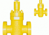
Maximum working pressure 21 MPa, 35 MPa, Size 2 1/6 , 3 1/8 USE: The valve is designed for wellhead equipment, Christmas trees and as a component of manifolds for production of crude oll and natural gas. Temperature class P, material class AA, or BB, PSL 1, PR 1. Technical parameters: Gate valve is duat closing fitting, manually operated. Body and bonnet are low-alloy steel castings. Gate, seats and nut for AA material class are made from low-alloy steel, for BB material class they are made from stainless steel. The spindle is made from stainless steel. Closed and open position can be reached by turning operating wheel all the way. The valve is connected by flanges with dimensions according to API Spec 6A.
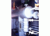
Test separator is used fo testing of free deposit water from produced natural gas. Gas is flowing into the separator through the neck Hl. Gaseous and liquid phases get separated due to stroke on deflector through internal construction. Gaseous phase is flowing out trough the neck H2 and further it continues into technological process. Liquid phase is collected on the bottom of the vessel horizontal part and in vertical cylindrical vessel it is automatically discharged through the neck H3 ( Fig.2). Manufacturer will supply test separator also as separate functional unit (Fig.1)built into warming object with temperature treatment including electric lighting and hot-water heating. Constituent parts of this unit are: - pipe branches for draining and gases including armatures - test measuring orifice track DN 150 PN 100 - measuring and adjusting devices and aquipment including conection and supplywith control medium Manufacturer produces technological pressure euquipment following customer´s technical requirements up to the volume 100 m3. Production Time: 6-8 weeks / Typical delivery time up to 4-5 months
Gas heater is used for increasing of natural gas temerature intechnological process of its production, processing, transportation and storage. Increased gas temperature prevents formation of hydrates and gas freezing during pressure expansion and in winter time. The heater consist in four main parts: 1. Heater shell with insulation filled in with heat – conveying medium 2. Flue with a cover 3. Heating coil with a cover 4. Heating and combustion system with measuring and regulation Supply options: I. II. separate heater body with flue and heating coil fixed on supports or skids complete heater with combustion system completed with measuring andregulation In accordance with customer´s request it is possible to manufacture also heaters with bester perfomances. Heating coil can be manufactured in various diameter and pressure dimensions (max.25MPa) Production Time: 1,5-2 months (
- Design according to the customer´s specification - Fabrication and Erection of Petrol Stations - Fabrication and Installation of Double Wall Storage Tanks - Turn – Key delivery - EN Standarts and Certificates - Maintenance works Production Time: 2 months /Typical delivery & installation time: 3-4 month
Double - shell tank is designed for construction of underground fuels storage of oil substances. It allows construction of ecologically safe storage of mentioned substances, which from the point of view of STN / SN 65 0201 standard belong to combustible liquids of 1st class of danger. Tand construction takes into account requirements of STN / SN 65 0201 standard Flammable liquids - Plants and storage rooms , SNT / SN 75 34 15 standard Plants for fandling of petroleum matters and their storage , STN / SN 69 0005 standard Stationary pressureless vessels - technical rules . The inner vessel shell is designed for bestest working pressure in inter-shell space 0,045 MPa. Wall thickness is designed with allowance for corrosion min. 1 mm. Inner tank represents operational part. Outer shell creates a protection for inner tank and prevents stored substance to eventual leakage out into surroundings. Inner tank shell as well as outer shell is welded from steel plates. Cylindrical parts are closed by vaulted bottoms according to DIN 6 608 standard. Both shells are liquid tight and separated each from other by delimitation plates, which also avoid their mutual displacement. Inter - shell space serves for indication of inner, respectively outer shell damage. Production Time: 6 weeks / Typical delivery time: 3-4 month
V rámci našich výrobných kapacít ponúkame zákazkovú kovovýrobu a zámočnícke práce.
Nabízíme: - Výroba z nerezových ocelí - Nerezové výrobky pro potravinářský průmysl - Výroba ocelových konstrukcí a průmyslových aplikací - Dopravní systémy - Brány, schodiště - Obrábění kovů - Opravy průmyslových zařízení - Stavba turistických vyhlídkových věží i z kombinovaných materiálů - Svařování ocelí, nerezu a hliníku - Svařence až do 2,5 t - a další…
Univerzálne stavebnicové priemyselné odsávacie a filtračné zariadenia – pre brúsenie – vysokopodtlakový systém – s asynchrónnymi motormi Použitie: Tieto malé stavebnicové priemyselné odsávacie a filtračné zariadenia s asynchrónnym motorom a meničom sú určené pre odsávanie nečistôt pri brúsení . Lokálne odsávanie škodlivín vznikajúcich pri brúsení a podobných technológiách vyhovujúce pre pracoviská s viaczmennou prevádzkou, skriňa agregátu je zameniteľná so skriňou agregátu s komutátorovým motorom (pri 1-zmennej prevádzke) . Pri ich prevádzke je používané široké príslušenstvo ako pre ručné tak i strojné brúsenie, prevádzka odsávačov môže byť so zariadením umožňujúcim spúšťanie odsávacej filtračnej jednotky v závislosti na spúšťaní odsávanej brúsky . Sú vhodné do 2-zmennej prevádzky . TYP: SOS AM 101.3.B Technické parametre odsávacieho a filtračného zariadenia: - Výška = 112 cm - Šírka = 32 cm - Dĺžka = 32 cm - Regulácia výkonu = ÁNO - Prierez filtr. modulu = 32 x 32 cm - Priemer sania = 40 mm - Použitie = brúsenie - Napätie = 230 V - Maximálny prietok = 180 m3/h - Maximálny podtlak = 15 kPa - Menovitý prúd = 4,5 A - Hmotnosť = 28 kg - Hluk = 72 dBA - Filter 1. stupeň = 6 kapsový filter FITEVIG 500, VIKAFIL, FIAB, FITEX, pl. = 1,0 m2 - Príkon = 1000 W TYP: SOS AM 201.3.B Technické parametre odsávacieho a filtračného zariadenia: - Výška = 120 cm - Šírka = 45 cm - Dĺžka = 45 cm - Regulácia výkonu = ÁNO - Prierez filtr. modulu = 45 x 45 cm - Priemer sania = 80 mm - Použitie = brúsenie - Napätie = 230 V, 400 V - Maximálny prietok = 350 m3/h - Maximálny podtlak = 15 kPa - Menovitý prúd = 9 A - Hmotnosť = 49 kg - Hluk = 75 dBA - Filter 1. stupeň = 9 kapsový FITEVIG 500, VIKAFIL, FIAB FLP 3, pl. = 3,2 m2 - Príkon = 2000 W Stavebnicové odsávacie zariadenia EKO ® - Šetrí za Vás Vaše pľúca i náklady